This site is best viewed at 1024 x 768
The FAMOUS R.A.F. R1116A Receiver - By Peter Park GM3PIP
|
The R1116A dates back
to the 1930s and was built to be used along with the T1116 Transmitter.
They were installed / fitted in the Sunderland Flying Boats &
the well known Fairy Swordfish Aircraft in late 1930s & in the
early years of W.W.2 Voltages required to operate the R1116A, were batteries delivering voltages of HT =120 volts, Grid-Bias=10.5 volts & 2 volts for Heaters/Filaments of the valves. The R1116A & the T1115
were the forerunners of the well-known R1155 & T1154, the main
transmitter / receiver communication equipment used in famous Lancaster
Bombers during the war. |
|
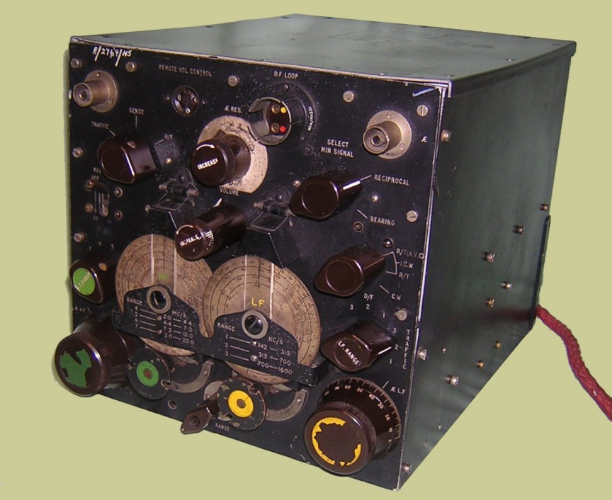
This picture of the front of the receiver you can
see the two tuning dails, HF and LF. Yellow is L F, Green is H F The
colour code,I think was taken up in the tuning controls etc. of the
R1155 / T1154 TX/RX. you can also see the thick red lead with the socket
on the end, that is the audio output for headphones / speaker,it comes
out at the rear of the RX.
|
|
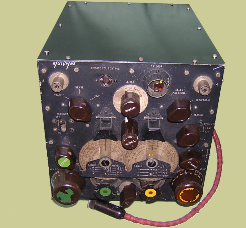
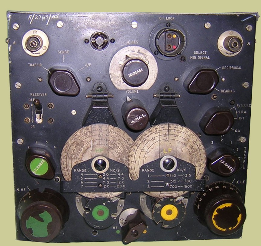
Front of the R1116A receiver showing you all the controls
of the receiver. If you study the controls on the front panel it gives
you a very good insight of the FAMOUS R.A.F. R1116A Receiver.
|
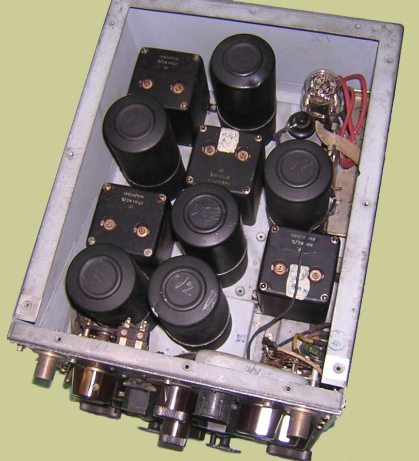
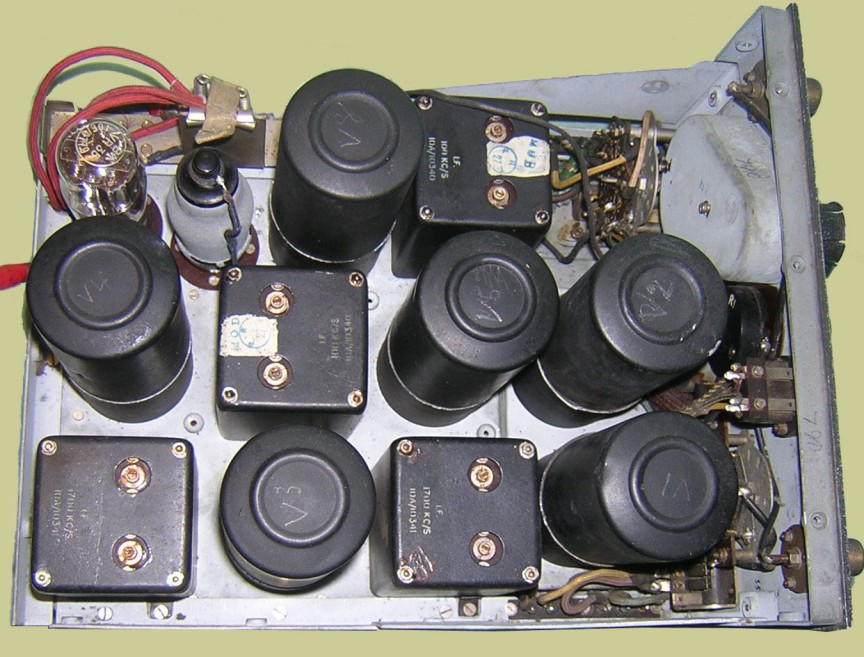
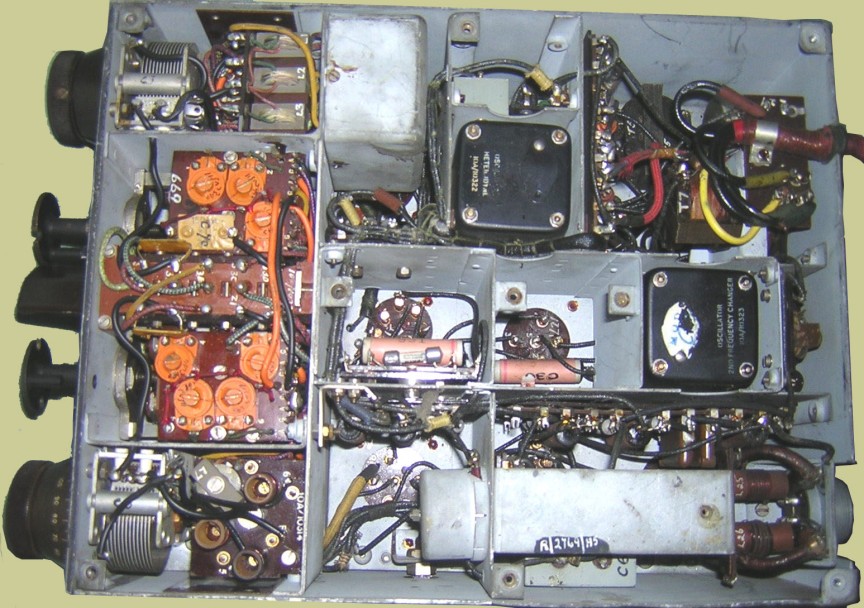
Again looking down on the receiver.
|
The receiver with its side panels back on, you can
see that the valve cans have been removed and showing the vintage screw
on top caps.
|
|
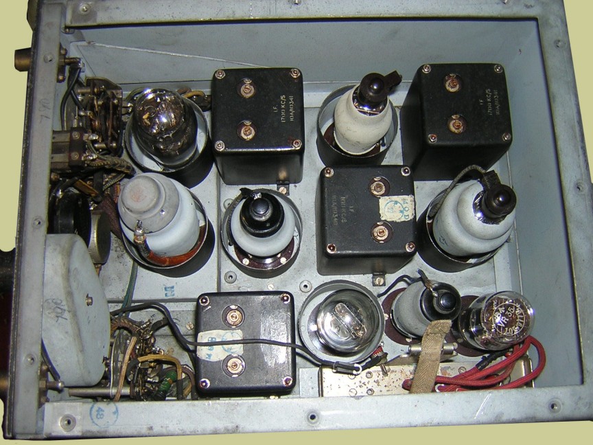
Looking down on top of the R1116A you see the six
valve screening cans, two of the valves are not screened, (VR44 and
VR35 ). The thin red leads top left is the bias battery connection leads.
|
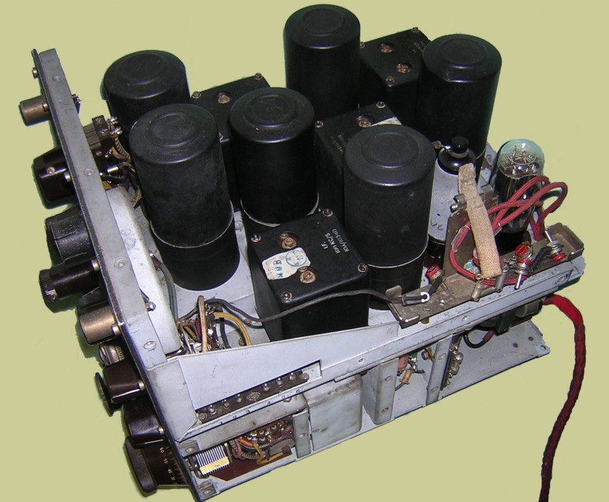
Top and sides removed, righthand corner is the bias battery compartment.
The nice steel chassis can be seen with its lovely rigid compartments.
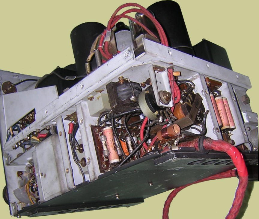
The audio output can be seen ( thick red cable ) it brought out the output
via phone socket for speaker/headphones.
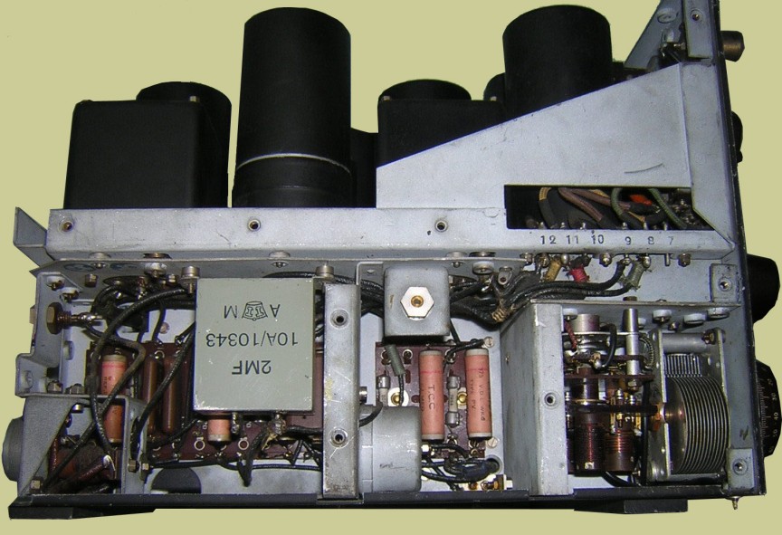
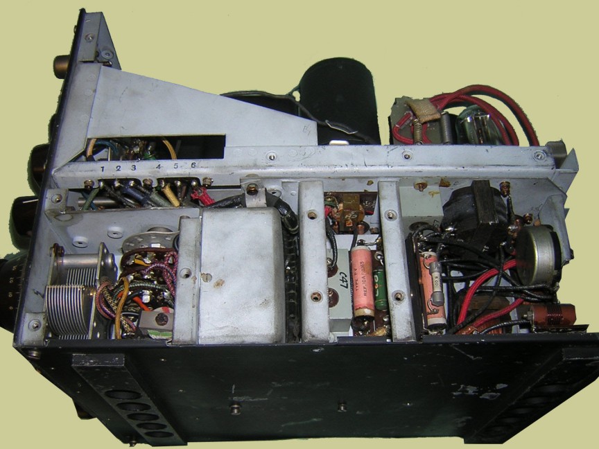
lefthand side Again you can see the nice compartments and thr vintage components.
Bottom far-right is the HF aerial tuning control.
Shows he two aerial tuning capacitors and the two waveband change switches,again
the well setout compartments.
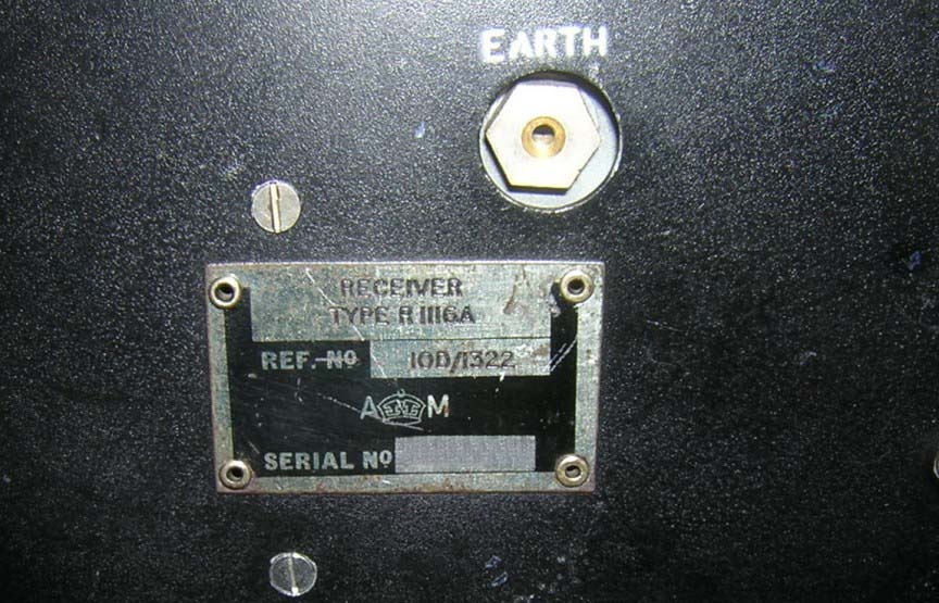
Air Ministry Plate. Ref. Reg.No.10D/1322.